

Infrared Thermography
Since the Space Shuttle Columbia accident, NASA focused on improving advanced NDE techniques for the Reinforced Carbon-Carbon (RCC) panels that comprise the orbiter’s wing leading edge and nose cap. It is made from layers of rayon cloth graphitized and impregnated with a phenolic resin and coated with silicon-carbide. To satisfy the first recommendation of the Columbia Accident Investigation Board, NASA investigated numerous nondestructive evaluation (NDE) methods for certifying the integrity of the orbiter’s wing leading edge RCC materials. Among the NDE methods investigated for use on the RCC materials were advanced digital radiography, high resolution computed tomography, thermography, advanced ultrasound, and advanced eddy current systems. Ultimately, NASA selected thermography as the first inspection step for RCC panels. Thermography’s advantages are that it is a fast, non-contacting, one-sided application, easy to implement in the orbiter’s servicing environment, and it detects the critical flaws of interest. Beginning in August 2005 this system was successfully deployed into the OPF at KSC and has been used for the inspection of both the wings and nose cap of the Space Shuttle Discovery following STS-114. Because of OPF clearance limitations it is necessary to have a custom “right angle” hood built to accommodate in-situ inspection of the orbiter wings.
 Photograph of the manipulator system and the “right angle” hood/camera assembly performing an inspection in the OPF at KSC on the Space Shuttle Discovery following STS-114.
Current Research
Process Monitoring for Additive Manufacturing
Research has also been conducted to use thermography as a process control monitoring system for additive manufacturing processes. On the NASA-developed Electron Beam Free Form Fabrication system (EBF3), which additively creates near-net-shape metal parts using an electron beam and metal wire feed, thermal cameras have been set up to monitor the metal melt pool during fabrication to better control the quality of the final part. This type of technology is also being applied to Automated Fiber Placement systems to mitigate carbon fiber manufacturing defects.
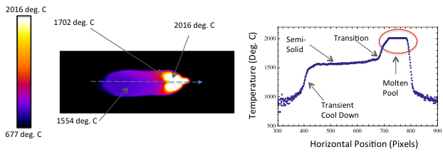 Infrared and temperature line plot on stainless steel
Thermography Success Stories
Success Story: Thermography Selected as Primary Inspection of Space Shuttle Wings Between Missions
Since the Space Shuttle Columbia accident, NASA focused on improving advanced NDE techniques for the Reinforced Carbon-Carbon (RCC) panels that comprise the orbiter’s wing leading edge and nose cap. It is made from layers of rayon cloth graphitized and impregnated with a phenolic resin and coated with silicon-carbide. To satisfy the first recommendation of the Columbia Accident Investigation Board, NASA investigated numerous nondestructive evaluation (NDE) methods for certifying the integrity of the orbiter’s wing leading edge RCC materials. Among the NDE methods investigated for use on the RCC materials were advanced digital radiography, high resolution computed tomography, thermography, advanced ultrasound, and advanced eddy current systems. Ultimately, NASA selected thermography as the first inspection step for RCC panels. Thermography’s advantages are that it is a fast, non-contacting, one-sided application, easy to implement in the orbiter’s servicing environment, and it detects the critical flaws of interest. Beginning in August 2005 this system was successfully deployed into the OPF at KSC and has been used for the inspection of both the wings and nose cap of the Space Shuttle Discovery following STS-114. Because of OPF clearance limitations it is necessary to have a custom “right angle” hood built to accommodate in-situ inspection of the orbiter wings.

Photograph of the manipulator system and the “right angle” hood/camera assembly performing an inspection in the OPF at KSC on the Space Shuttle Discovery following STS-114.
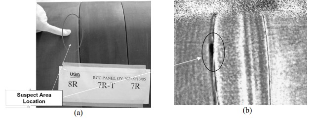
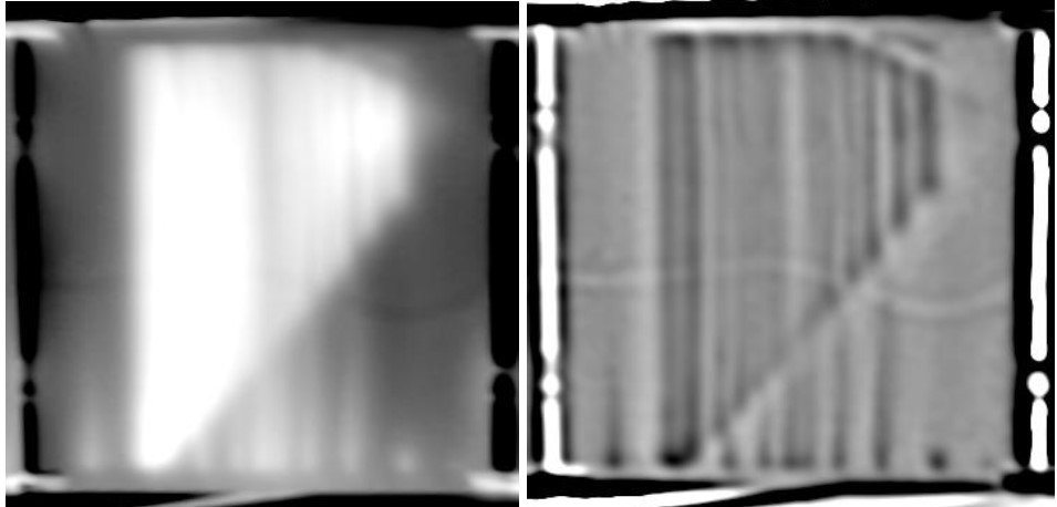
Typical results of the thermal inspections performed on Discovery. (a) Shows a photograph of the inspection area with a suspect location indicated. (b) PCA processed thermal image of the same area also showing the suspect damage region.
Success Story: On-orbit EVA IR Camera Developed For Detection of Subsurface Damage in Shuttle Wing Leading Edge. Currently Resides on ISS as NDE Instrument Available for Inspections of Solar Panels, Interior instrumentation inspections, and others.
The EVA IR Camera expanded the capabilities of the thermal NDE methodology to enable inspection of the Thermal Protection System (TPS) by an astronaut during an Extravehicular Activity (EVA)
The EVA IR Camera System has completed three flight tests and has operated successfully each time it has been used in orbit. To date the camera has acquired over 450 Mbytes of on-orbit infrared imagery. All mission objectives have been met, and both the camera and the inspection procedure have been effectively demonstrated. A mature NDE technology for detecting subsurface damage in RCC on the ground has been successfully transitioned and demonstrated as an orbital inspection technique. It has been shown that subsurface delaminations as small as 2.54 cm. in diameter and 75% deep in the RCC panel can be detected with this camera system using passive solar heating.
The development of inspection tools for the Orbiter’s Thermal Protection System (TPS) was critical to NASA’s Return-to-Flight efforts. Infrared thermography is capable of detecting both surface and subsurface damage that could have been caused by an in-service event, such as delaminations, silicon-carbide coating loss, and surface cracks typically seen in the presence of subsurface delaminations. The Shuttle Astronaut Crew Office established requirements for a hand-held system for inspecting the TPS. This operational concept is illustrated in Figure 1 below.
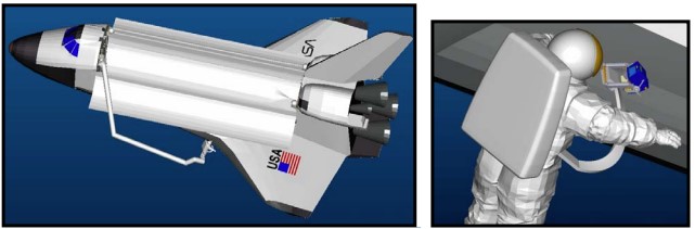 Figure 1. Operational concept: IR Inspection via astronaut EVA.
To provide an external heat source for the inspection, solar energy is used. This approach reduced the system weight, power, and development time requirements by avoiding the need for a secondary heat source, but places an operational constraint on the measurement as the data must necessarily be taken during the daylight portion of the orbit.
To validate the performance of the infrared imager and inspection concept, the EVA IR Camera was tested during two Shuttle missions: STS-121 and STS-155 and one ISS EVA. The major objectives of this effort were (1) the development of an operational concept, (2) development of an infrared camera suitable for space operation, (3) transitioning the inspection technique and analysis software for orbital boundary conditions, (4) measurement of the thermal boundary conditions seen by the wing leading edge during orbit, and (5) inspection and characterization of damaged RCC samples during orbit
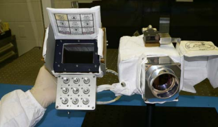
EVA IR Camera Flight Unit. Currently stored and available for use on the ISS

(A) Infrared image from Shuttle wing leading edge taken at 07:16 CDT on July 15, 2006. Orbital sunrise will occur in approximately 5 minutes. (B) Temperature versus time plots for two regions of the infrared image.
Results for camera tests conducted during the stage EVA on the ISS (Figure 11) resulted in detection of defects approximately 2.5 cm. in diameter created from panel impact and 4 flat-bottom-hole simulated damage regions ranging in size from 2.5 cm in diameter to 5 cm in diameter with 25% material loss from the back surface.
 Astronaut Thomas Reiter prepares the Test Article Assembly for data acquisition. (B) Processed thermal images of acquired data.
The EVA IR Camera is stored on the ISS, and has been used for other inspections as appropriate, such as the inspection of the cooling tubes in a damaged radiator panel.
 (A) Photograph of damaged ISS Radiator Panel, (B) Thermal Image from EVA IR Camera, (C) Processed thermal image

Each cooling tube was analyzed by plotting its temperature along the length of the tube, and the analogous tube in each panel directly evaluated. Temperature profiles for underperforming cooling tubes are readily apparent.
Select Publications
Cramer, Elliott & Winfree, William & Hodges, Kenneth & Koshti, Ajay & Ryan, Daniel & Reinhardt, Walter. (2006). Status of thermal NDT of space shuttle materials at NASA. Proceedings of SPIE - The International Society for Optical Engineering. 6205. 10.1117/12.669684.
Howell, Patricia & Winfree, William & Cramer, Elliott. (2005). Infrared On-orbit Inspection of Shuttle Orbiter Reinforced Carbon Carbon Using Solar Heating. Proc SPIE. 10.1117/12.615332.
Rotter, Henry A., International Space Station (ISS) Heat Rejection Subsystem (HRS) Radiator Face Sheet Damage, NASA/TM-2012-217348, NESC-RP-09-00529.